


INTRODUCTION OF ASUNARO AOKI CONSTRUCTION TECHNOLOGY
UNITING GROUP MEMBERS
TOWARDS A POWERFUL LABORATORY THAT PROVIDES TECHNOLOGICAL RESOLUTIONS FOR SOCIAL DEMANDS
INTRODUCTION
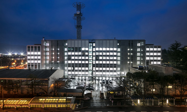
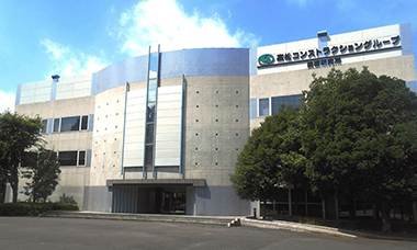
Asunaro Aoki Construction Technology (AACT, Photo 1) opened in Tsukuba Research Gakuen City, which has been leading the world in science and technology since 1993. The AACT is located in an area rich with nature and adjacent to the University of Tsukuba. Presently, the campus of AACT is known as the “Takamatsu Construction Group Technology Research Institute,” where our company is the core of a group of companies sharing the campus, including the Takamatsu Construction Company and other member companies.
Due to aging of the facilities, equipment, and experimental equipment over the past 24 years since the opening of our campus, a total renewal has been carried out since 2013. The number of staff was also increased to create a research unit capable of providing technical resolutions for social requirements such as “strengthening the country’s land” and “strategies for an aging social infrastructure.”
The motto of our company is “Based on our unique technology, we provide high-quality and low-cost products, completely satisfying our customers’ expectations, and fulfilling our company mission of contributing to society by developing our business.” This is the key criteria for us as a “C & C (Consultant & Construct) Company.” Furthermore, we are doing our best to improve the value of our company by developing technologies.
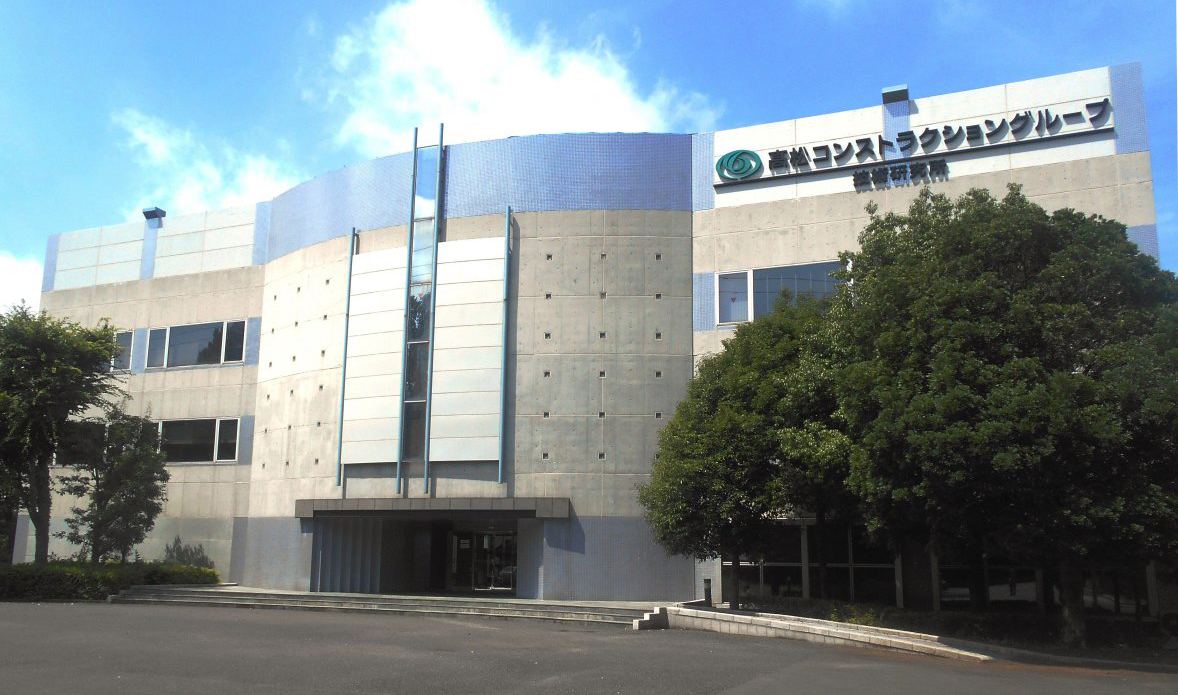 Photo 1 Technology Institute
OUTLINE OF THE INSTITUTE OF TECHNOLOGY RESEARCH
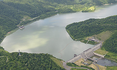
The Technical Research Institute campus covers an area of about 18,000 m², with a construction area of about 3,000 m² and a total floor area of about 9,000 m². There is a management building and an experimental building, along with outdoor experimental yards, aggregate yard, and aggregate testing rooms (Photo 2).
The main building is an RC building, which has three floors on the ground and one floor underground. The facilities in the main building include an entrance hall, an exhibition room, a presentation room known as the “technical dream factory,” a large conference room, a library, and several laboratories.
The large roof structure between the experimental building and the management building is utilized as an experimental building for large structures (Photo 3). A large reaction force wall (12 m high × 17 m wide × 2.5 m-thick prestressed concrete construction) with a large reactive force floor (width 17 m × 20 m) is located at the center of the experimental building. There are four large capacity actuators in the building, permitting structural experiments for civil engineering and architectural purposes.
In the large structural experiment building and the general laboratory building, there are environmental chambers and durability test instruments capable of creating various environmental conditions. Thanks to the apparatus, a lot of important achievements have been obtained in technical development such as earthquake-resistant buildings, mixed buildings, and high-rise RC buildings.
The following are some of the major facilities and the presentation room, shown in the photos below (photos 4 to 7). Photo 8 shows placement situations and exhibits the building design and construction process to the public to aid their understanding.
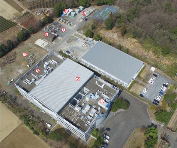 Photo 2 Technology institute
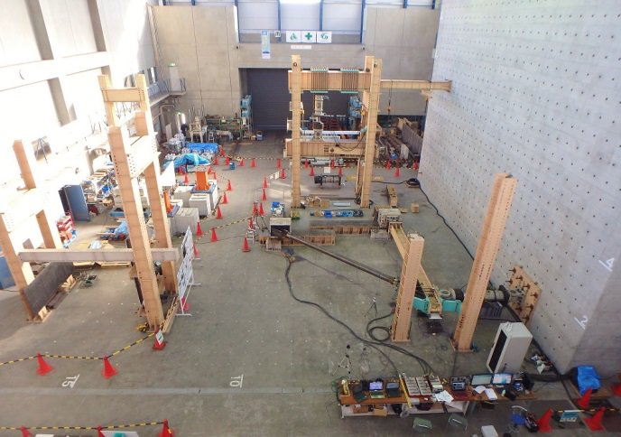 Photo 3 Large structural experiment building
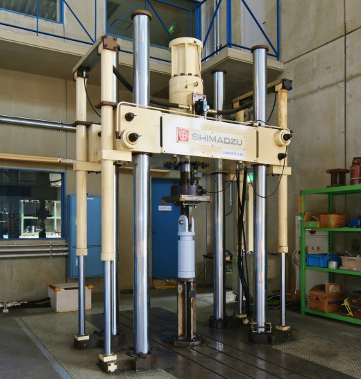 Photo 4 Large-scale fatigue testing machine
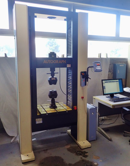 Photo 5 Precision universal testing machine
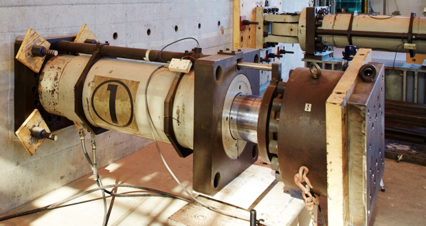 Photo 6 2000 kN large capacity actuator
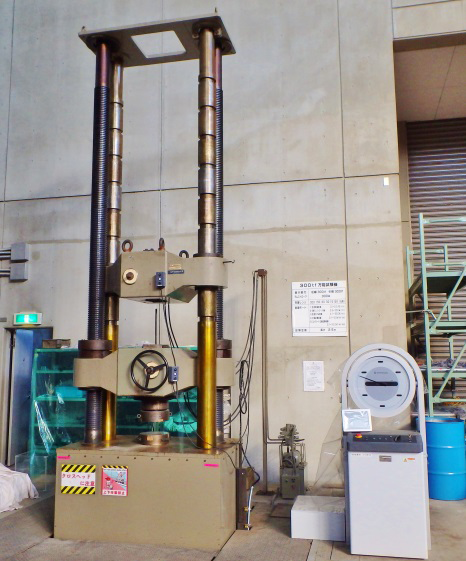 Photo 7 3000 kN universal testing machine
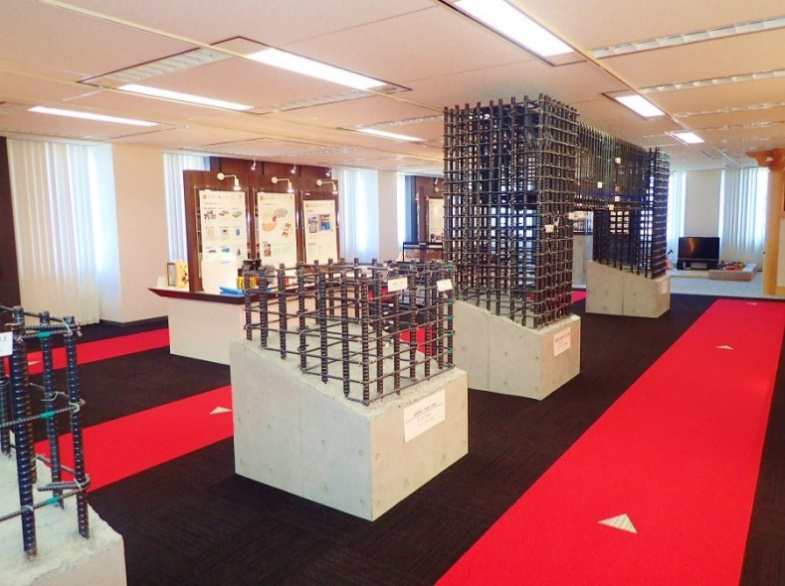 Photo 8 Internal exhibition of the “technical dream factory”
INSTITUTE OF TECHNOLOGY RESEARCH INSTITUTE
The Technical Research Institute is under the management of the headquarters of our group company. There are four laboratories (the Civil Engineering Laboratory, Building Laboratory, Earthquake Renewal Laboratory, and Environmental Laboratory), a Planning and Management Office (including Intellectual Property Management), a Civil Renewal Division, and a Takamatsu Laboratory at the institute. As of April 2017, there are 37 people enrolled in the institute, including 6 female researchers.
Each laboratory is responsible for special technical development of the entire construction field, such as civil engineering, construction, environment, and disaster prevention. The Institute of Technology is engaged in technological development aiming at application ten years from now, in cooperation with the technical headquarters and the new business headquarters at the headquarters of our group company.
EXAMPLES OF TECHNOLOGY DEVELOPMENT
Technologies developed at the Technical Research Laboratories are commercialized for business development. Five representative examples, including three examples under development, are given as follows.
EXAMPLES OF BUSINESS DEVELOPMENT FROM TECHNICAL DEVELOPMENT
(1) SEISMIC RETROFITTING METHOD USING DAMPING BRACES
1) BACKGROUND OF DEVELOPMENT
Considering the increasing interest in earthquake resistance for buildings, we have developed and actively applied seismic retrofitting methods as reinforcement techniques enabling construction while the buildings are used as usual. A brace (friction damping built-in brace [damping brace]) was attached to the outer wall of a building (Photo 9), having improved earthquake resistance performance by absorbing the energy from the swaying of the building in an earthquake.
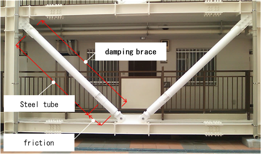 Photo 9 Installation status of a damping brace
2) RESEARCH AND DEVELOPMENT
The following analytical research and experimental developments were carried out for medium- and low-rise RC buildings.
Prior to practical application, various phenomena were reproduced by numerical analysis, the results of which improved performance reliability. Marginal performance tests of friction dampers, deterioration promotion tests, and atmospheric exposure tests, etc., were also conducted, the results of which confirmed that there was no problem in practical application.
A full-scale structure experiment was conducted as a culmination of our research and development. This reinforcement method was applied to a pseudo dynamic experiment using three reinforced RC buildings, the results of which confirmed the damping reinforcement effect on the actual structure.
These results were summarized and compiled for a guideline for design and construction, which received a technical evaluation from the Japan Building Disaster Prevention Association.
3) APPLICATION RESULTS
There are more than 60 application examples so far, including a wide application to public buildings such as schools and government buildings. In recent years, application to private buildings (especially multi-family houses) accounts for a large proportion (Photo 10).
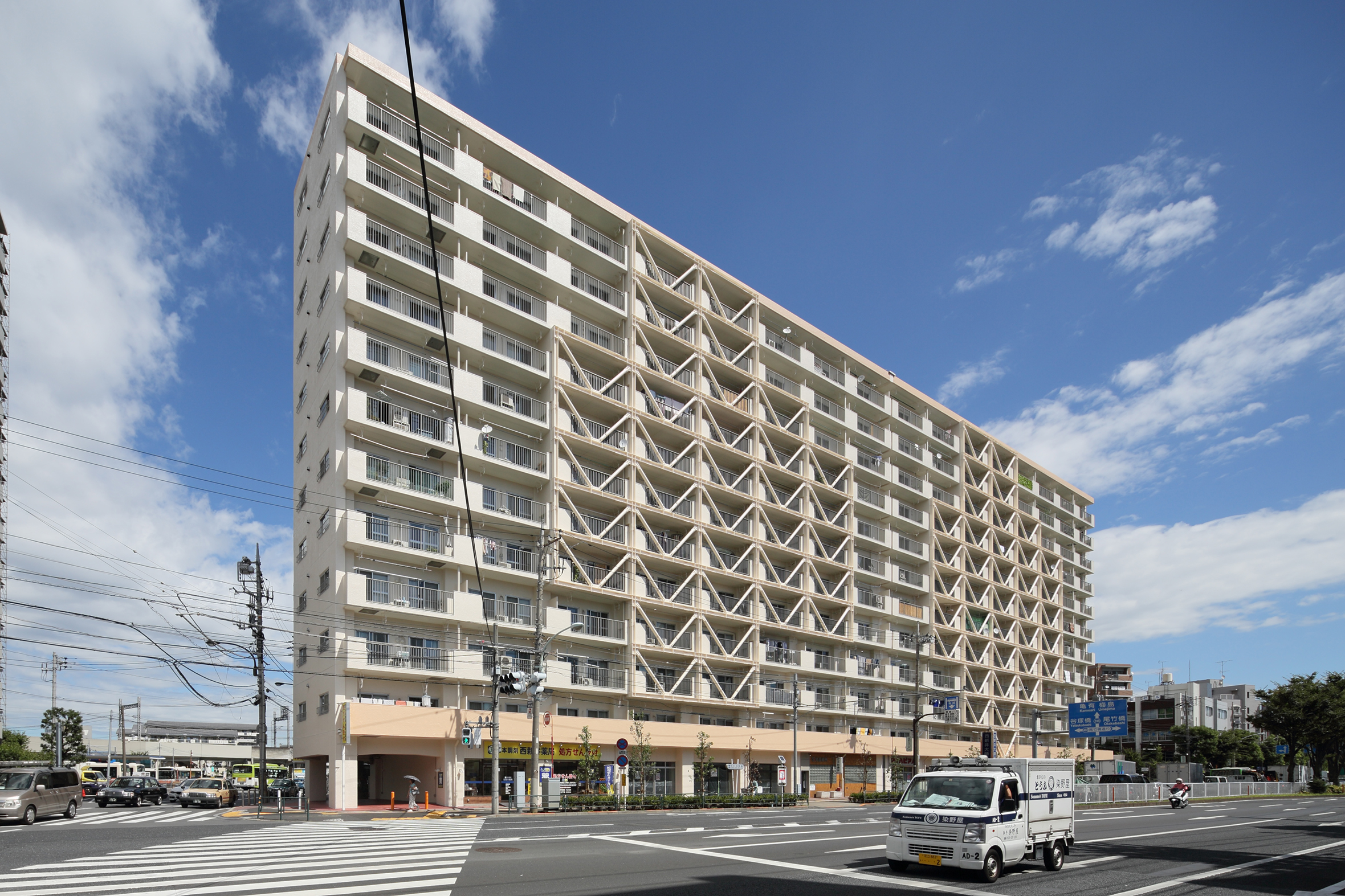 Photo 10 Installation status of the control shock brace
(2) SEISMIC CEILING CONSTRUCTION METHOD (AA-TEC CONSTRUCTION METHOD)
1) BACKGROUND OF DEVELOPMENT
Due to the high degree of ceiling damage that occurred in the Great East Japan Earthquake, a law amendment took effect in 2014, in which the maximum horizontal seismic intensity up to 2.2 G for a specific ceiling (ceiling height exceeding 6 m and ceiling area exceeding 200 m²) corresponding to high earthquake resistance performance is required.
Therefore, we jointly developed the “AA-TEC construction method” with Tokiwa Industry Co., Ltd. as our corresponding earthquake-resistant ceiling construction method (Fig. 1). We compiled the design and construction method and acquired a building technology performance certificate (BVJ – PA 16 – 001) from the Bureau Veritas Japan Co., Ltd. on October 13.
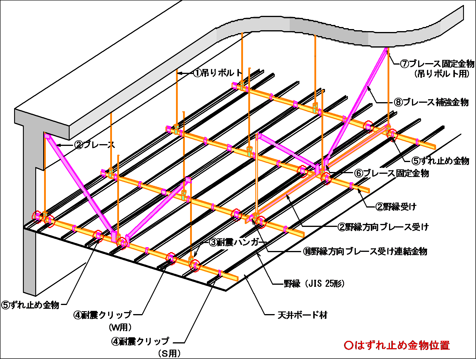 Fig.1 Overview of AA-TEC construction method
2) RESEARCH AND DEVELOPMENT
This method uses an earthquake resistant ceiling with an allowable strength of 9,000 N per unit (horizontal units of horizontal ceiling area that one pair of braces can handle) corresponding to a maximum horizontal seismic intensity of 2.2 G. Regardless of the structure calculation system of the building’s main body, the official procedures for this technique can be processed after simple confirmation review and are applicable to new buildings of RC, SRC, and S construction.
The results of the performance confirmation experiments showed that the ceiling hanging length covered a range of 0.5 m – 1.5 m, and the ceiling area up to 30 m² per unit can be borne (Photo 11).
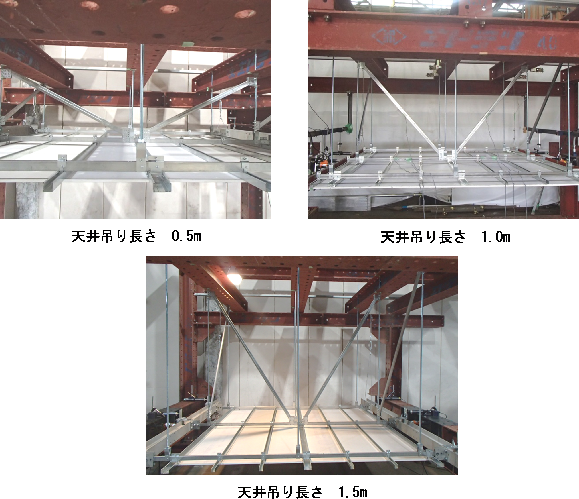 Photo 11 Experimental situation on seismic ceiling construction
3) FUTURE DEVELOPMENT
The present method can be applied not only to specific ceilings but also to other room spaces, except for those outdoors. Taking advantage of the acquisition of the building technology performance certificate, we are trying to establish an earthquake ceiling penetration association (one company) to promote the spread of seismic ceilings and to build a better social infrastructure.
EXAMPLES UNDER DEVELOPMENT
(1) IMPROVEMENT OF EARTHQUAKE RESISTANT BRIDGES USING FRICTION DAMPERS
1) OUTLINE OF DEVELOPMENT
Die/rod-type friction dampers (hereinafter referred to as friction dampers) utilize the frictional force generated at the contact surface between the die (metal rod) and the rod (metal ring) as shown in Fig. 2. They have been applied to a number of construction projects as seismic reinforcement strategies for the building structures introduced in Section 3-1(1).
These friction dampers have been applied to the development of construction methods that improve the earthquake resistance of bridges in collaboration with the Metropolitan Expressway Co., Ltd. (Fig. 3). By adopting this construction method, the friction dampers were installed on bridges and halved the damage of the pier base in comparison to bridges without friction dampers.
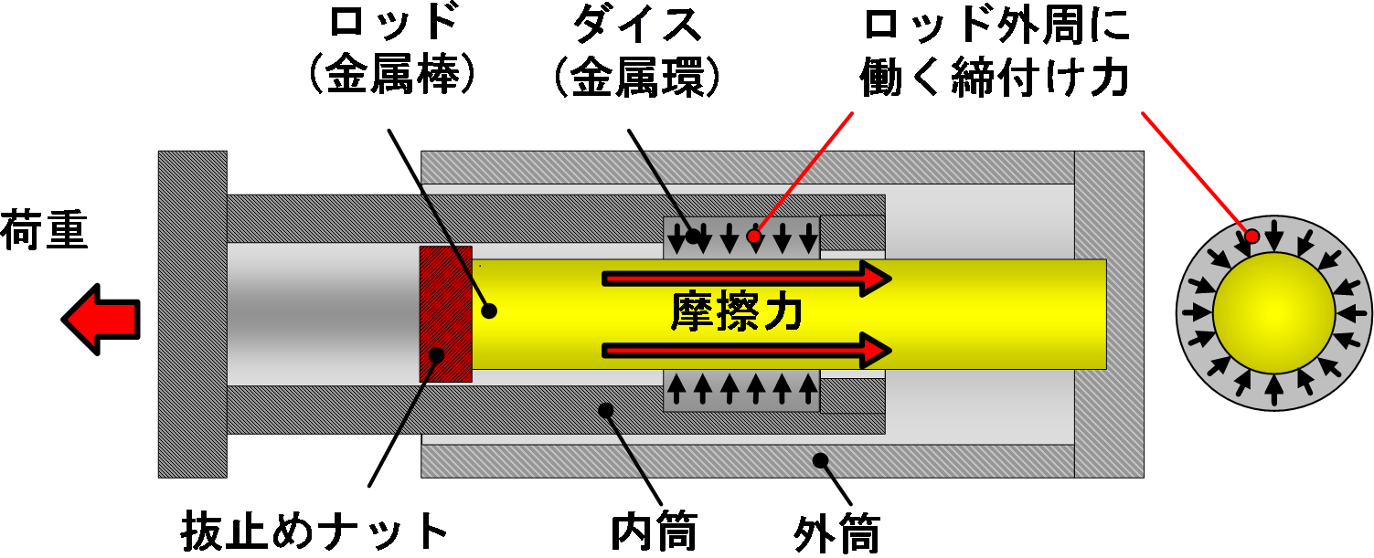 Fig.2 Overview drawing of a friction damper
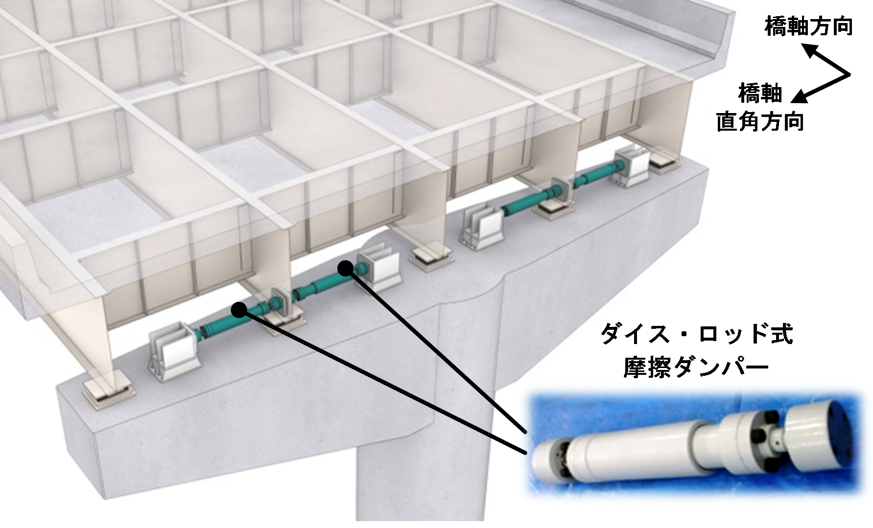 Fig.3 Bridge seismic resistance method using friction dampers
2) RESEARCH AND DEVELOPMENT
Fig. 4 shows the state of a shaking table experiment which reproduces the dynamic behavior of an actual earthquake, where a large-scale bridge model with a friction damper was constructed to simulate a single RC single pillar bridge with a two-mass system (National Institute of Advanced Industrial Science and Technology).
The experiment was carried out from January to March 2016 by using a large three-dimensional vibration shaking instrument owned by the Civil Engineering Laboratory. The results of the experiment showed that this bridge earthquake resistance construction method provided excellent earthquake resistance.
As shown in Photo 12, a performance confirmation experiment using a “large capacity friction damper” with friction load ± 900 kN and maximum stroke ± 350 mm was carried out in order to apply the friction damper to a large-scale bridge under various design and construction conditions. This experiment was conducted in December 2016 using the large jack system described above.
The experimental results demonstrated excellent seismic performance using large capacity friction dampers.
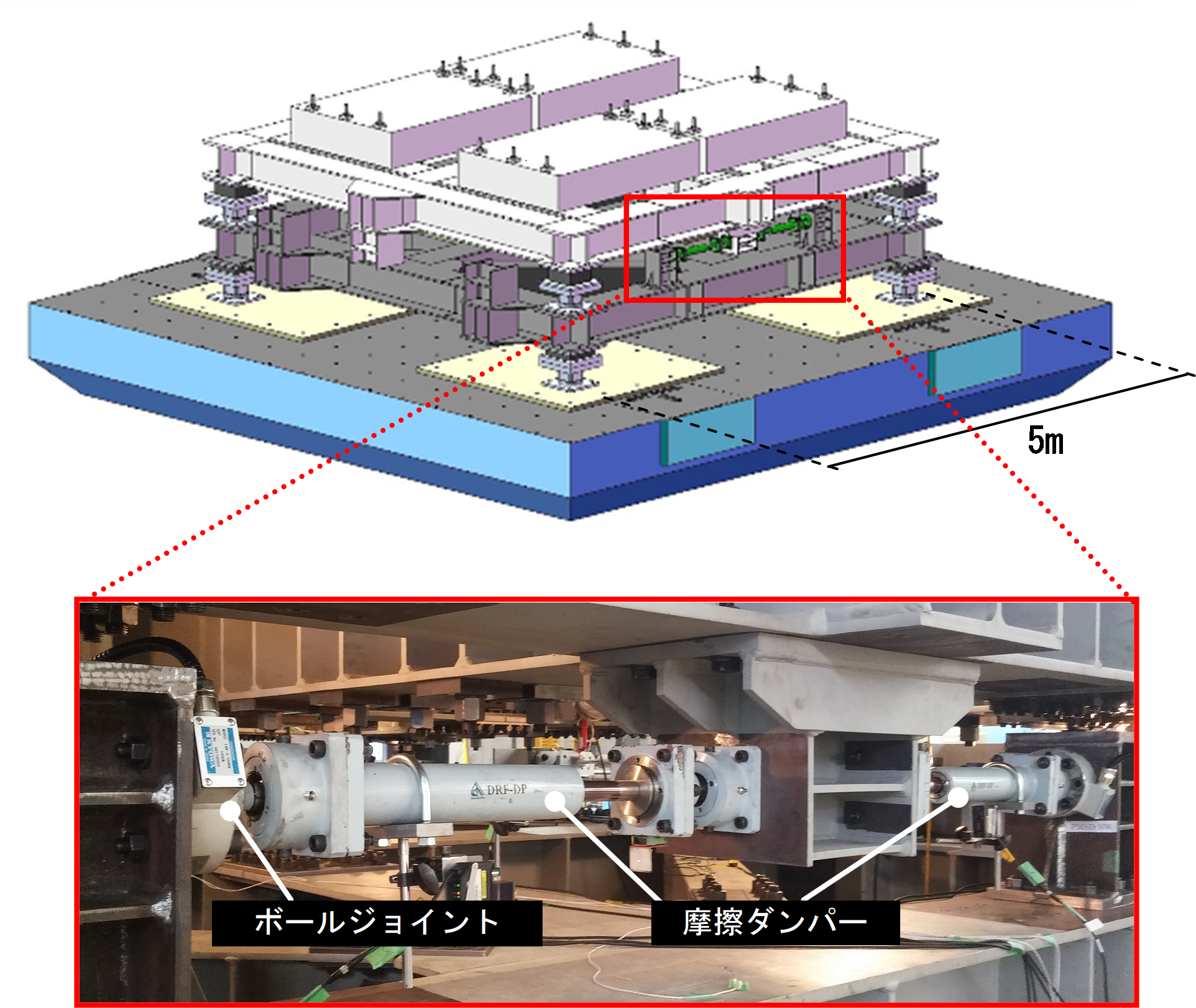 Fig.4 Shaking table test for large scale bridge model
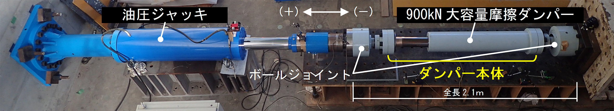 Photo 12 Confirmation of the performance of a large capacity friction damper
3) FUTURE DEVELOPMENT
We are planning to utilize the friction side blocks, which were developed together with the friction dampers, for large-scale renovations, renovations of expressways, and other applications.
(2) PERFORMANCE CONFIRMATION EXPERIMENT USING A FOLDED BRACE
1) OUTLINE OF DEVELOPMENT
The folded brace is an earthquake-resistant brace made by joining three steel materials in a single stroke manner so that the actual length is three times the apparent member length. Since the actual length is much longer than the apparent member length, the axial yield displacement increases by 2 to 2.5 times compared to a conventional earthquake-resistant brace (Fig. 5).
We acquired a Structural Performance Evaluation (ERI – K 12009) from Japan ERI Co., Ltd. in April 2013 and have applied this technique to a number of projects.
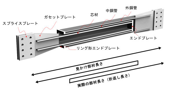 Fig.5 Outline drawing of folded brace
2) PERFORMANCE CONFIRMATION EXPERIMENT
This experiment was carried out in January 2017 in order to confirm whether the actual large turn-up brace using a circular steel pipe, which had been planned to be applied to new properties, possessed the structural performance (axial yielding displacement increase effect and buckling restraint effect) assumed by the design (Photo 13, Fig. 6).
The results of the experiment confirmed that the structure possessed the structural performance (axially yielding displacement increasing effect, buckling restraining effect, etc.) assumed by the design. Judging by the large deformation on the compression side, it was confirmed that buckling was not observed even when the deformation was equivalent to an interlinear deformation angle R = 1/50 rad.
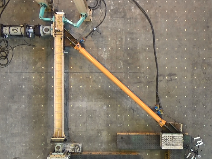 Photo 13 Test situation of a load applied to a folded brace
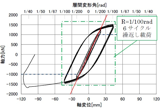 Fig.6 Axial force-axial displacement relationship
3) FUTURE DEVELOPMENT
Even in office buildings and factories where we previously had to abandon the brace structure, we can now utilize a brace structure superior in earthquake resistance and economic efficiency because it can be arranged eccentrically and in small amounts. From now on, we are planning to pursue further development of this technology as well as trying to expand the scope of its application.
(3) PERFORMANCE CONFIRMATION EXPERIMENT OF COMPOSITE TYPE EXPOSED COLUMN FOOT
1) OUTLINE OF DEVELOPMENT
The composite type exposed column base is a new type of column base, “a combination of anchor bolt yielding type and base plate yielding type,” developed independently by our company (Fig. 7).
It features a higher efficiency of absorbing seismic energy than conventional pedestal legs and high earthquake resistance. Furthermore, it does not require any special steel materials. Its production and construction are the same as that of the conventional exposed type pedestal, and it has the additional merit of keeping construction costs down to about half of the exposed column base legs using special steel materials.
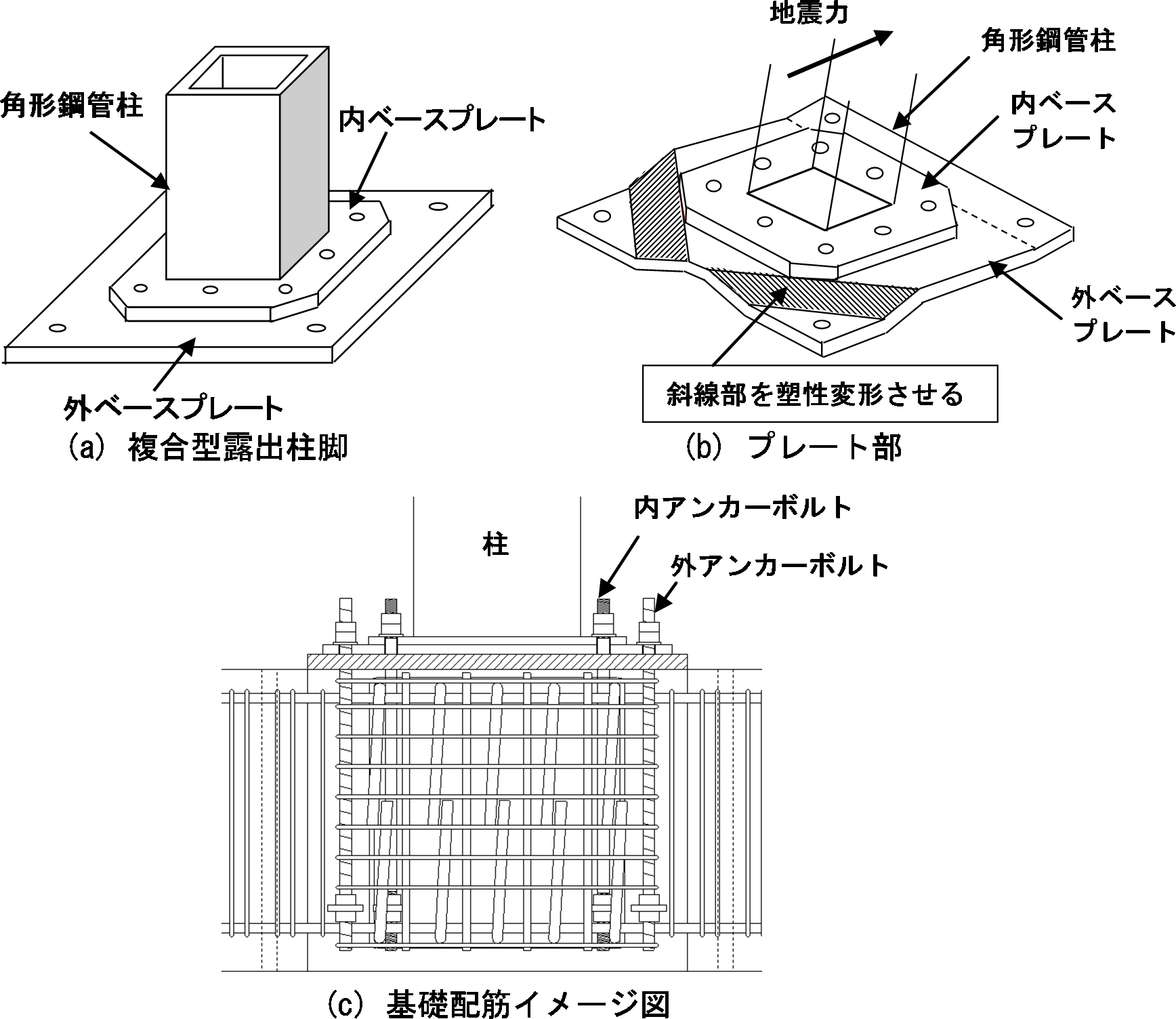 Fig.7 Outline drawing of composite type exposed column base
2) PERFORMANCE CONFIRMATION EXPERIMENT
A specimen simulating a 550 mm square column and foundation beam was made and applied in an experiment confirming the strength, rigidity, and deformability of the pedestal by applying a horizontal force (earthquake assumed) to the column. It was also applied to confirm the extent of performance recovery after repair (Photo 14).
The experimental results confirmed that a higher seismic performance than from a conventional anchor-bolt yield base pedestal was obtained due to the yield effect of the base plate. It was also confirmed that energy can be absorbed stably for cyclic loading due to the plasticizing of the base plate (Fig. 8).
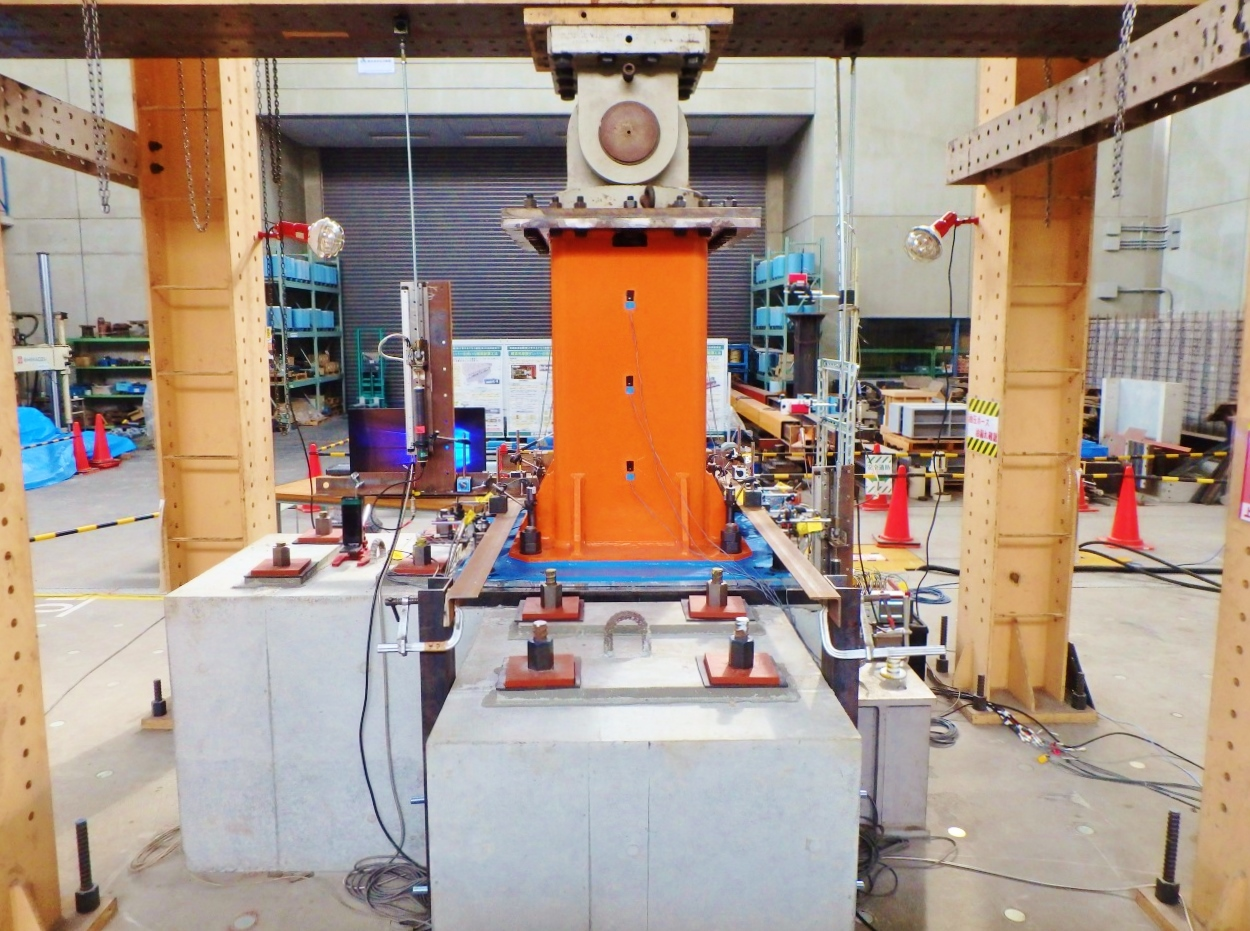 Photo 14 Combined exposed column base upper load test status
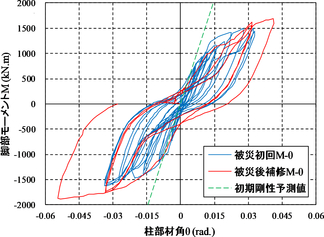 Fig.8 Column base moment and angle of rotation of column relation
3) FUTURE DEVELOPMENT
Compound type exposed column base legs can distribute the earthquake energy generated on the first floor of a building in a well-balanced manner to the upper floors. From now on, we are trying to acquire a technical evaluation and promote the dissemination of this technique so as to accelerate the pace at which we build a better social infrastructure.
CONCLUSION
As the Director of the Technology Research Institute, I will continue to share my enthusiasm for construction technical developments with younger technical staff, in line with the principles we have held since the founding of our company. It is our duty and responsibility to carry out further technical developments and to make progress for the entire Takamatsu Construction Group.
While the achievements of the Research Institute of Technology are widely available to customers as construction methods and products, it is also important to publish reports and papers both within and outside the company, and to contribute to society and the community by conducting academic activities. I will do my best to promote these activities.
Fortunately, the domestic construction market is steadily expanding due to the steady increase in public investments such as social infrastructure development and renovation leading up to the Tokyo Olympics and Paralympic Games in 2020, in addition to private capital investments. We will take this opportunity and work on appropriate themes corresponding to construction demand, for example, working on the “high quality” and “high function” demands of our customers as we strive for the sustainable development of society.
 Contact Us